




EVA Case Interior Systems: Foam Inserts, Molded Trays and Divider Systems for Multi-Component Product Kits
A protective case is only as good as what happens to the product after the shell stops moving. Buyers often judge a case by its exterior: the molded EVA shell, the zipper, the color, the dimensions on the specification sheet. Yet in real transit and real field use, the component that actually prevents damage is the interior retention system. The outer case can survive a one-meter drop with zero visible damage while the items inside slide, collide and scratch each other beyond repair. This article focuses on the design of internal fixing and storage systems for EVA cases, and how to engineer them for multi-component product kits.
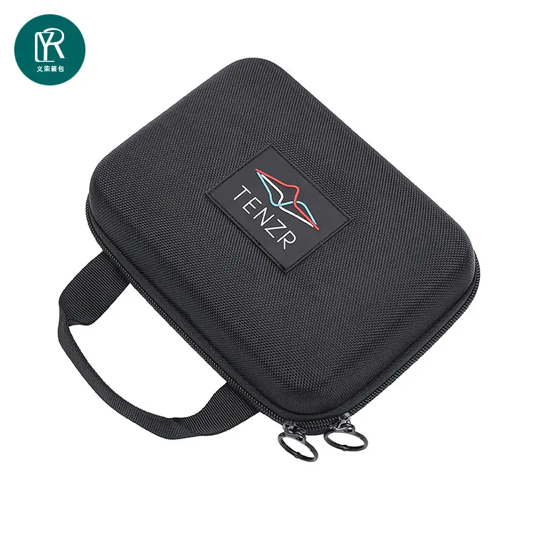
Why the Interior Fixing System Decides Success or Failure
The most common failure mode we see from importers is not a broken shell. It is a shell that looks perfect, opened to reveal a scratched lens, a chipped housing, a bent bracket or a detached control knob. The impact energy that the shell absorbed was transferred straight through a loose or poorly shaped liner and into the product. A hard tool pressed against an unpadded wall leaves a rub mark after a few hours of road vibration. Two metal parts stored in one oversized pocket knock against each other and develop edge nicks.
We have reviewed a returned shipment where the carton and the EVA case both passed visual inspection, but nearly thirty percent of the units inside arrived with surface scratches on a polished bezel. The root cause was a foam cavity that was cut one millimeter too wide, allowing the part to shift during transit. The shell did its job. The interior did not. For any brand that cares about first-open experience, the interior fixing system is the real quality gate, not the outer molding.
The Special Difficulty of Multi-Component Kit Packaging
A single-product case is comparatively simple: one shaped pocket, one secure item. A kit is a different problem entirely because it introduces three distinct challenges that do not exist for single items. The first is completeness, meaning every item on the bill of materials must have a visible, dedicated place so packers and customers can confirm nothing is missing. The second is retrieval order, because many kits are used in a sequence: the main unit first, then cables, then smaller accessories, then documentation.
The third challenge is preventing wrong takes. Kits frequently contain parts that look similar but are not interchangeable, such as two brackets of different lengths or two connectors with close specifications. When cavities are generic boxes, a user grabs the wrong part and the assembly fails in the field. Good kit design turns the case into a visual checklist: each pocket is shaped or labeled for exactly one part, so an empty cavity is immediately obvious and a wrong part does not fit cleanly. This is where interior design stops being packaging and starts being part of the product experience.
Die-Cut Foam: Choosing Density and Rebound for EVA, PU and PE
Die-cut foam remains the workhorse of EVA case interiors, and the central decision is foam grade. We have covered material fundamentals in our published guide EVA Foam Density, Molding Process and Shock Absorption, so this section focuses only on selection logic rather than material science. The three common choices are EVA foam, PU foam and PE foam, and each behaves differently under load.
EVA foam offers a good balance of firmness, cost and durability, and it is easy to die-cut into precise cavities. PU foam is softer and more compressible, which suits fragile items that need gentle contact pressure but can lose shape faster. PE foam has higher chemical resistance and a closed-cell structure that resists moisture and crumbling. Within any family, density and rebound matter more than buyers expect: a heavier rigid tool needs a higher-density foam so it does not bottom out, while a light fragile item benefits from a softer foam with higher rebound so it settles back after each impact. Selecting the wrong grade is the silent cause of both bottoming-out damage and premature liner fatigue.
Multi-Layer Structures and Retrieval Hierarchy
When a kit grows beyond a shallow tray, the interior must be organized in layers, and the layer order should follow how the user actually works. A multi-layer nesting approach stacks trays or foam decks so the most-frequently used item sits on top and the rarely used items sit deeper. There are three common mechanical styles.
The flip-top style places a hinged foam or tray deck above a lower compartment, so lifting the lid reveals the top layer and flipping it open reveals the second. The pull-out style uses sliding trays that extend like drawers, useful when the case is too deep to reach into comfortably. The nested style stacks fully removable trays, each sized to the parts it holds, so the whole deck lifts out for bench work. The right choice depends on how the case is opened in practice: a field technician standing up prefers pull-out or flip-top, while a workshop user at a bench tolerates deeper nesting. Retrieval hierarchy is a usability decision, not just a packaging one.
Vacuum-Formed Trays: PET, PP and PS Considerations
Beyond cut foam, many kits use a vacuum-formed tray for a cleaner, more retail-ready look. The tray is thermoformed from a plastic sheet and snaps into the EVA case wall. The three mainstream materials are PET, PP and PS, and they trade off differently.
PET gives good clarity, stiffness and scratch resistance, which makes it the preferred choice for premium presentation and for trays where the product color should show through. PP offers better chemical resistance and flexibility, and it survives more aggressive environments without cracking. PS is the lowest-cost option and forms sharp detail, but it is more brittle and less suitable for rough transit. Wall thickness typically ranges from about 0.5 millimeter for light accessories to 1.5 millimeters or more for heavier components that need structural support. A practical question for importers is foldability: thin PET and PP trays can sometimes be supplied flat and folded by the assembler to save shipping volume, while thicker or heavily ribbed trays must ship pre-formed. Specifying foldable versus rigid early avoids a costly tooling change later.
Velcro Dividers and Adjustable Separators: Flexibility Versus Cost
Fixed die-cut cavities are precise but rigid: they fit one configuration forever. Velcro or hook-and-loop dividers let the user reconfigure the interior, which is attractive for kits that change over time or serve multiple product variants. The tradeoff is cost and consistency. A sewn Velcro grid is more expensive to produce than a single die-cut foam deck, and it relies on the user to place dividers correctly, which reintroduces the wrong-take risk that fixed cavities solved.
In practice, the best designs mix the two. Critical, fragile or high-value items get fixed die-cut pockets, while generic accessories get an adjustable Velcro zone. This keeps the important parts safe and the variable parts flexible without paying for full adjustability everywhere. When quoting a program, we always ask whether the kit contents are stable; if they change every season, a partially adjustable interior is cheaper over the product life than re-cutting foam inserts every revision.
Mesh Pockets, Elastic Bands and Accessory Fixing
Not every item in a kit is a rigid component that needs a shaped cavity. Cables, manuals, warranty cards, small fasteners and flexible accessories are better held by soft retainers. Mesh pockets on the lid interior keep documents visible and breathable, and they let a user confirm at a glance that paperwork is present. Elastic bands or straps secure loose items such as power cords or a tablet pen so they do not wander into the main compartment.
These soft retainers are also the right home for items that are used last or set aside during work, because they are easy to drop in and pull out quickly without disturbing the precision foam below. The mistake we see most often is overloading a mesh pocket until the zipper or the lid cannot close, which then puts pressure on the rigid items underneath. Accessory fixing should be sized to the actual accessory, not to the largest object a user might try to force in.
Drop Energy Transfer: From Shell to Liner to Product
To understand why interior design matters, trace the energy path of a drop. The outer EVA shell takes the first impact and deforms locally. The die-cut foam inserts between the shell and the product then do the real protective work. Think of the foam as a spring with a nonlinear compression curve: under small loads it compresses easily, and as compression increases the resisting force rises sharply. During a drop, the foam absorbs kinetic energy by compressing, converting it into elastic deformation and a small amount of harmless plastic deformation.
The goal of the liner is to stretch the deceleration event over a longer distance and time, which lowers the peak g-force the product experiences. A cavity that is too tight transmits shock directly to the product; a cavity that is too loose lets the product accelerate and then slam into the foam wall. The ideal pocket holds the item with light preload, leaves a small compression travel, and surrounds rigid contact points with enough foam depth to ride the compression curve rather than bottom out. This is why sample drop testing with the real product matters more than comparing foam specifications on paper.
Tip: Always validate the interior with the actual production samples rather than 3D-printed mockups, because real foam rebound, wall thickness and cavity tolerance behave differently from engineering models.

Electrostatic-Sensitive Scenarios: Anti-Static Foam Basics
When the kit contains electronics, circuit boards or sensors, ordinary foam can be a hazard of a different kind. Static discharge during insertion or removal can damage sensitive components. The solution is a anti-static foam, but the terminology is often confused. Surface resistance is the practical metric: standard protective foam is insulating with very high resistance, static-dissipative foam sits around ten to the power of six to ten to the power of nine ohms per square, and conductive foam is below that range.
For most commercial electronics kits, static-dissipative foam is the safe middle ground: it bleeds charge away slowly without the aggressive conductivity that can interfere with some assemblies. Conductive, carbon-loaded foam is reserved for handling bare boards in controlled environments. The wrong choice is either ignoring the risk entirely or over-specifying conductive foam where it adds cost and handling complications. We recommend defining the target surface resistance range as part of the kit specification whenever the contents include anything with exposed circuitry.
Liner Service Life: Compression Set, Shedding and Powdering
A liner that performs perfectly on day one can fail after months of storage or repeated use, and importers rarely test for this. The first aging mechanism is compression set, the permanent deformation a foam retains after being compressed for a long time. A foam with high compression set slowly loses its grip, and cavities that once held parts snugly become loose, reintroducing the shift-and-scratch problem.
The second mechanism is shedding: low-quality or poorly bonded foam releases small particles that contaminate the product, a serious issue for optical, medical or cleanroom kits. The third is powdering, where certain foam formulations chalk or crumble as they age, especially under heat, UV exposure or repeated flexing. Service life should be specified as a requirement, not assumed. For programs with long shelf lives or harsh storage, we recommend requesting compression-set data and a short aging test rather than trusting a foam grade by name alone.
Printed and Embossed Position Labels with Assembly Guidance
Once the cavities are defined, the next step is telling the user where each part belongs. Printed position labels turn the interior into a self-explanatory system. Silk-screened labels on the lid or on the foam surface name each pocket, often with a part number or a small icon. Embossed or debossed markings achieve the same result without ink, which survives rough handling and cleaning better.
For complex kits, the interior can carry assembly work instructions directly: a numbered sequence printed near each cavity guides the user through correct build or teardown order. This is especially valuable for service kits where a technician must reassemble equipment correctly under time pressure. The label substrate must match the case environment: printed foam labels can wear, while laser-etched or embossed markings last the life of the case. Specifying the marking method during tooling avoids a later relabeling program.
Prototype Validation Checklist Before Mass Production
No interior design should go to mass production on paper alone. We recommend a four-step validation before approving tooling. First, fill the case with the actual production items, not substitutes, and confirm every cavity fits with the intended light preload and that no item is forced. Second, perform a real drop test from the specified height onto the specified surfaces, then open and inspect every component for movement marks or impact damage.
Third, repeat the take-and-place cycle many times to simulate field use, checking that pockets still hold and that nothing loosens or tears at the seams. Fourth, place the filled case in both high and low temperature conditions for a defined period, then recheck fit and foam recovery, because heat and cold change foam behavior and adhesive bonds. Only after these four steps pass should the interior be released for production. This checklist has caught more interior failures than any specification review, because it tests the system as a whole rather than its parts in isolation.
Related Pages
- EVA Tool Case Purchase Order Guide
- EVA Tool Case Sample Evaluation Guide
- EVA Case Bulk Order Tips
- EVA Tool Case Custom Inserts Design
Post time: Oct-21-2026